Assembling the xPRO V4 Case
Posted by Mike on 19th Dec 2018
In this article we will cover the assembly of the CNC xPRO V4 Case
STEP 1: Gather the supplies:
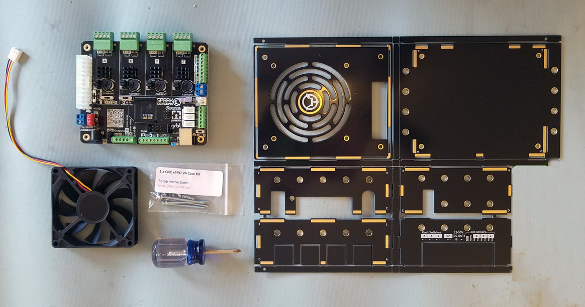
Things you need:
1 x CNC xPRO V4
1 x CNC xPRO V4 Case Kit (PCB, Fan, and hardware)
Screwdriver
Pliers (optional)
STEP 2: Snap out PCB panels. Simply bend on the score lines and snap the panels out (depending on shipping, some panels may be pre-snapped, sorry to steal some of the fun!). Use of pliers may be needed for some of the smaller areas. The end result should look like this
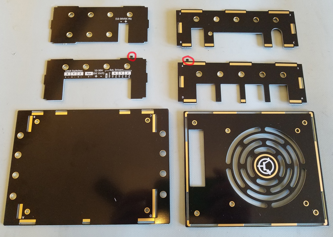
*Mind that the two mouse bites (marked in red above) are removed
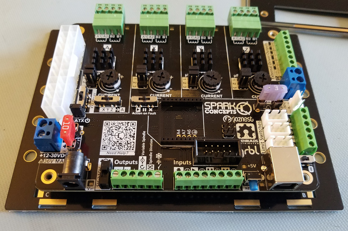
STEP 3: Mount the xPRO to the base plate using the four #4-40 x .25” bolts (the short, skinny ones included). Note orientation, the "B" label on the case should be by the USB jack.
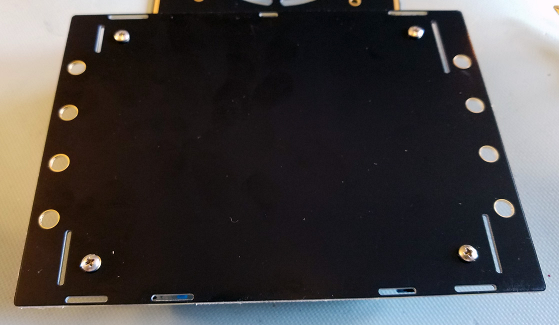
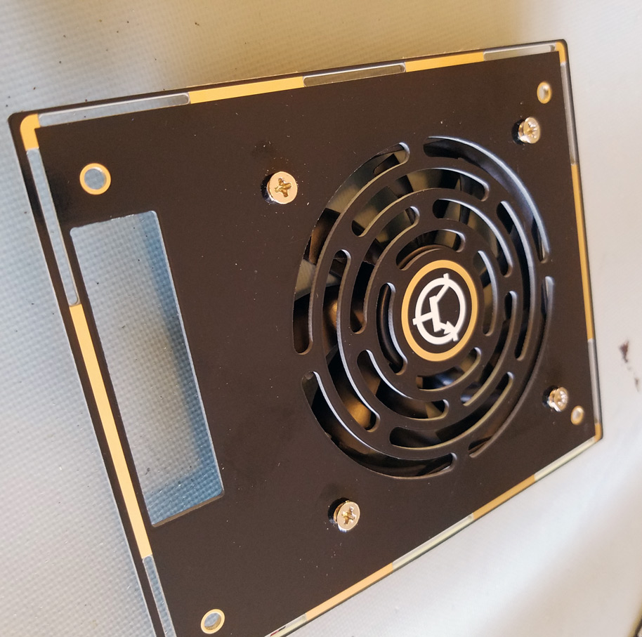
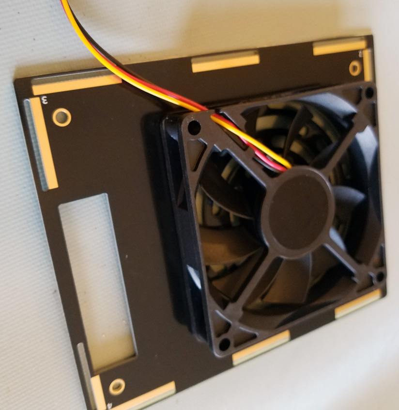
Step 4: Mount the fan on the inside of the top plate with the four M5 fan screws (the short, fat ones included). Note the PCB hole is tight, so the screw will thread through the PCB AND the fan. Install with “airflow” arrow pointed away from the top plate. Orient so fan wire is as shown below.
Step 5: Wire xPRO V4 to your CNC machine. DO NOT POWER
Step 6: Slide sidewalls into place over wiring.
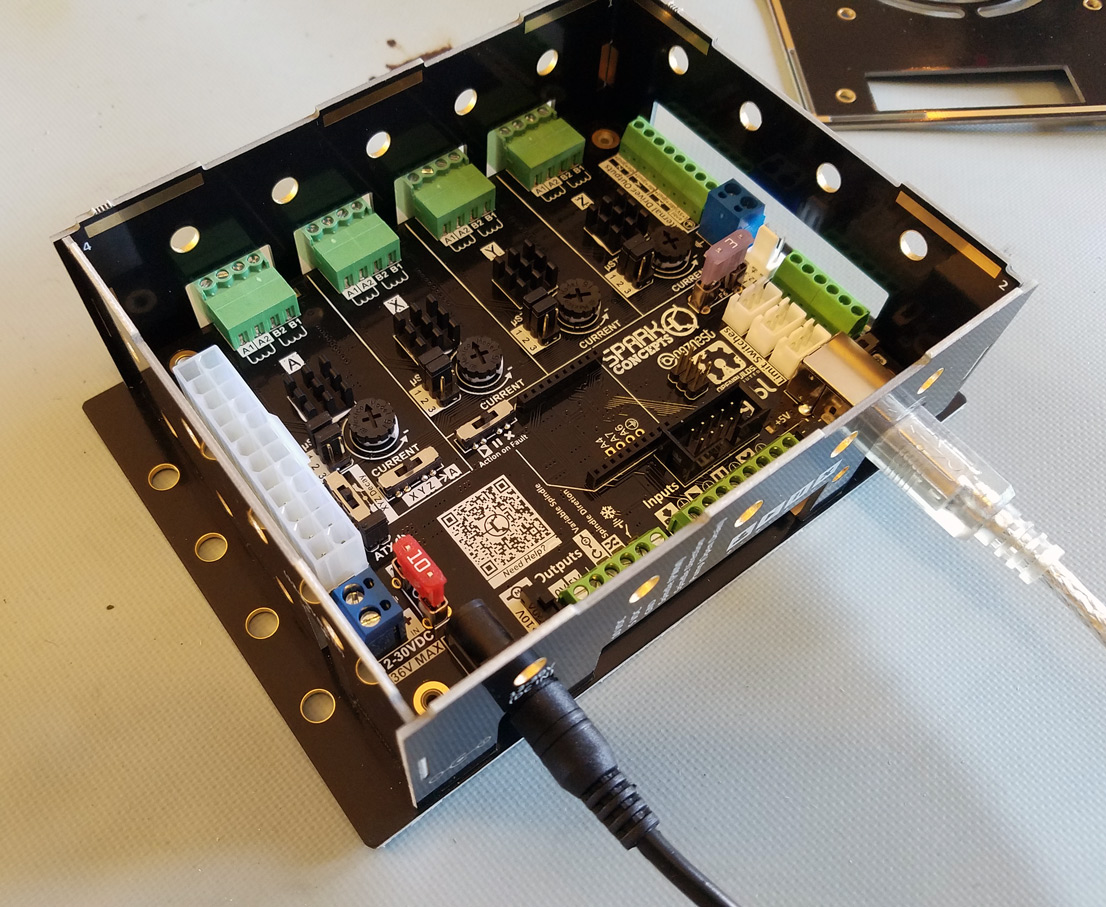
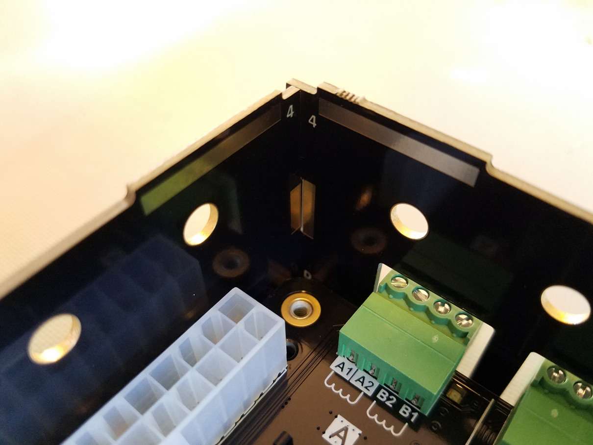
*Note: Each upper corner is marked with a unique number, each lower corner is marked with a unique letter to ensure orientation
Step 7: Plug the fan into the fan terminal on the xPRO. Note: connector is keyed so it will only go on one way
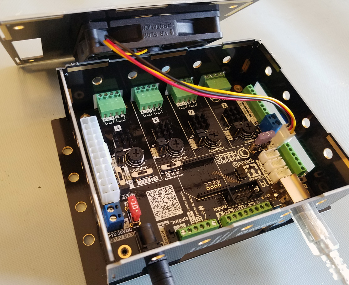
Step 8: With the fan down, place the top plate onto the sidewalls and attach. Use the #4-40 – 1 5/8” (long, skinny bolts included) and screw into the on board standoffs. Do not over-tighten screws here
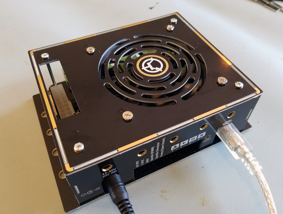
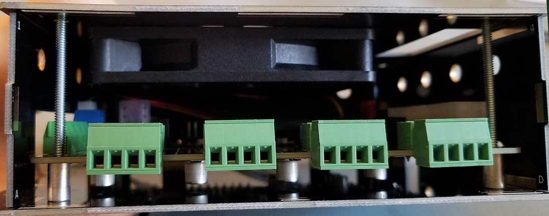
*Internal view of assembled case
Step 9: (optional) Mount case. This can be done with wood screws into a work table, double sided mounting tape, or M5 bolts and drop in Tnuts for Vslot profiles. (this hardware not included).
The included fan is a ball bearing fan to support vertical or horizontal installations but makes them slightly louder than sleeve bearing fans.


