

Limit Switches – a better way
Posted by Bill on 28th Dec 2018
tl;dr = If you experience noise on the limit switch (or false triggers), wire your limit switches as NC to ground, set $5=1. *bonus points – wire signal to common, NC to ground, and NO to 5V. This way you pull the signal low, and push the signal high when triggered.
Let’s talk about limits
Historically, limit switches have always caused a bit of heartburn. The original recommended designs used the internal pullup of the microcontroller, and a simple switch wired Normally Open (NO) to ground. When triggered the switch would pull the signal to ground initiating a subroutine in the firmware. Easy, simple, straightforward. However, stepper motors are inherently noisy and 2m long cables make GREAT antennas for picking up noise – end result is a lot of false trigger, a lot of effort into isolating signals, and a lot of shielded cabling. This is the default nature of GRBL, and embraced by many builds over the years so it will remain the recommended hookup.
It looks a little something like this:
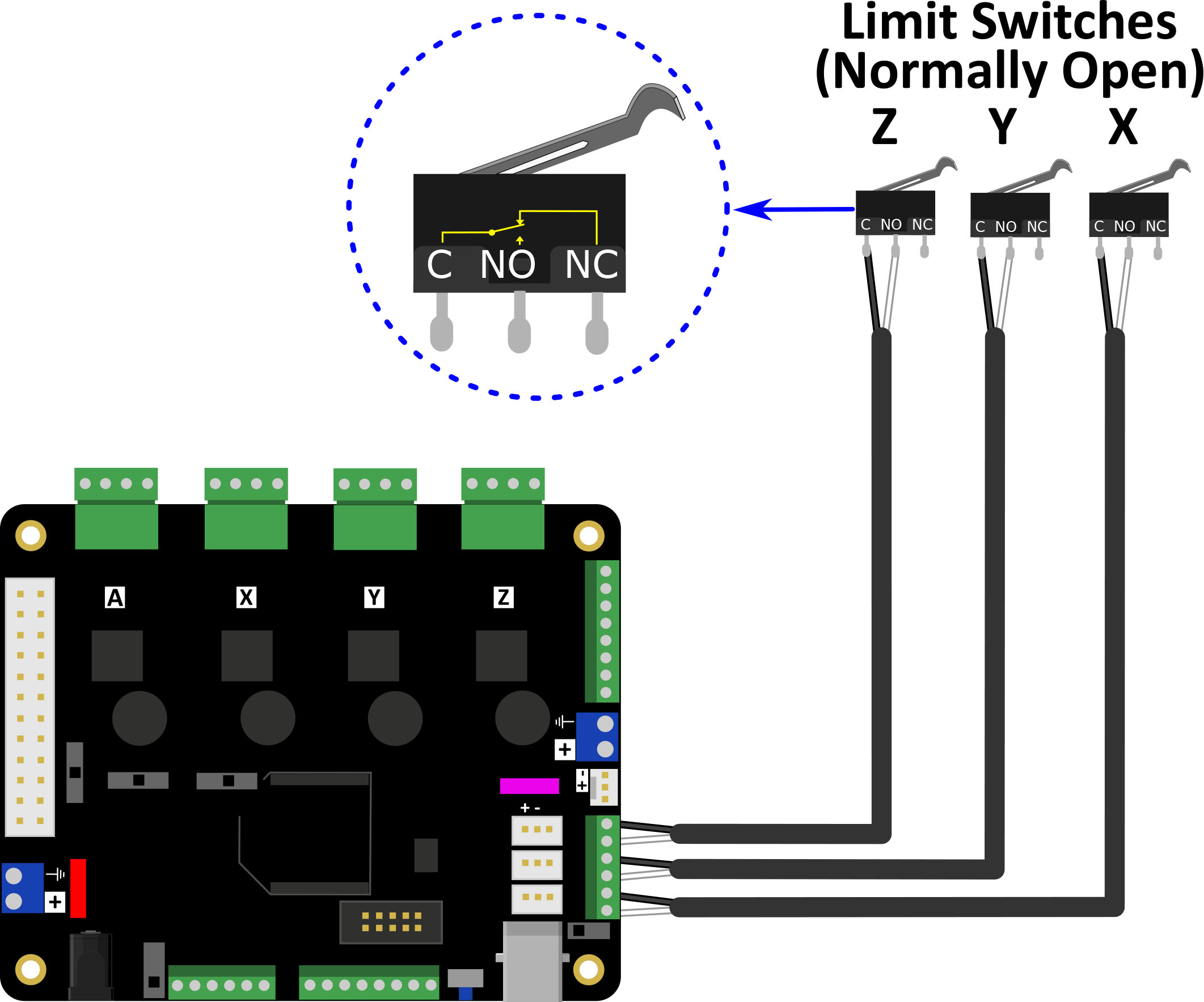
This setup works great IF you pay attention to cable routing and keep signal wires away from power wires (motor leads, AC/DC high current lines).
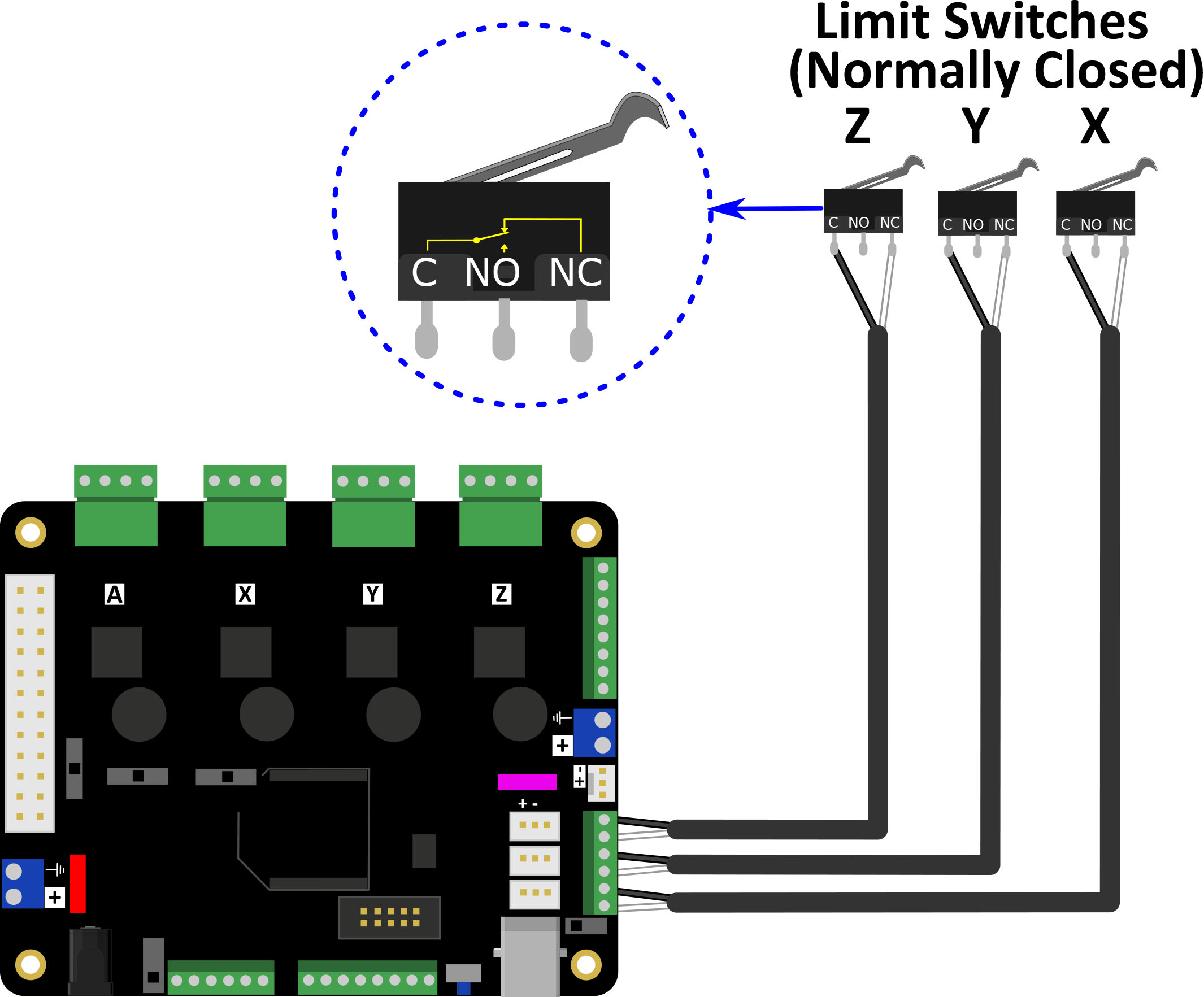
However, if this setup is giving you false triggers try wiring your limit switches as normally closed (NC) to ground. This will use the ground reference of the board and DC power supply to sink any noise the limit switch wires pickup. If you are using Homing, you will need to set $5=1 to invert the limit lines for homing. This will hold the limit signal low until the switch is triggered at which point, the signal will be pulled high by the internal pullup initiating a subroutine in the firmware. IF you currently have NO switches installed, these can typically be changed to NC switches by selecting the correct terminal on the switch.
It looks a little something like this
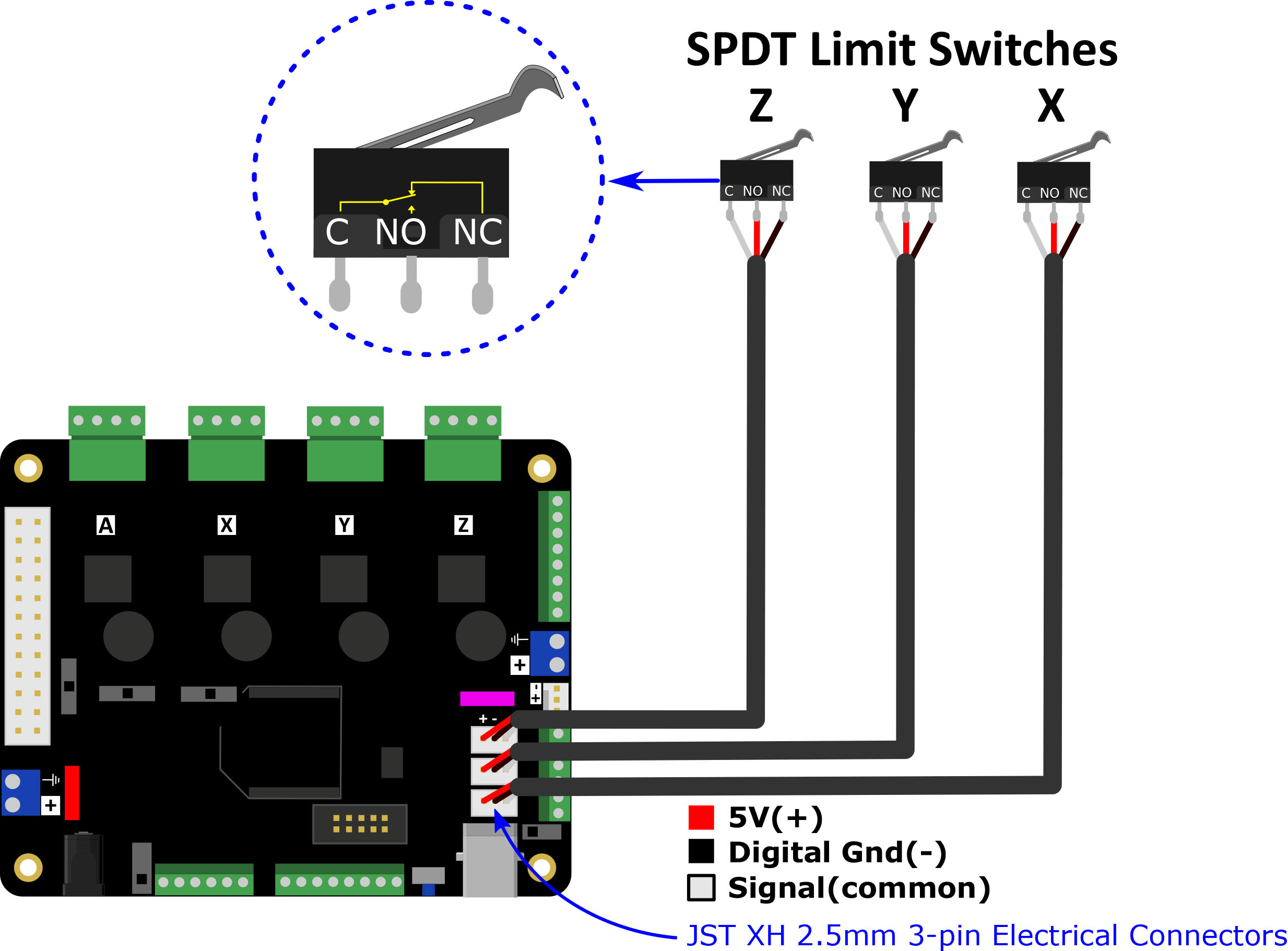
To make this even better, you can pull the limit down AND push the limit high (remember to set $5=1 still). To do this wire the signal to common, NC to ground, and NO to 5V. In this setup the limit signal is pulled low, sinking any noise, then when the switch is triggered the limit signal is driven high by the 5V connected to NO.
It looks a little something like this
Happy cutting!